While it’s important to fasten your seatbelt, my first ritual getting on the driver’s seat is to check on the fuel tank. That’s because I was once stranded on the road for failing to do so. Running out of fuel is an unpleasant experience, particularly if you’re already late for an appointment.
Call me obsessed, but I now have a habit of looking at the fuel gauge. I developed the same obsession, although in different ways, when it comes to electronic circuit design. That’s because neglecting certain rules or best practices had landed me in trouble before.
Critical Process Before Starting Electronic Circuit Design
Critical Process Before Starting Electronic Circuit Design
Before you start drawing the first schematic connection or visualizing the components needed, you’ll want to ensure that the design specification is well-drafted out. The design specification is a document drafted out from the requirements of a client or team lead.
The requirements often revolved on the features of the product and the applications of the electronics. As a PCB designer, you’ll want to ensure the requirements given are sufficient to translate into specifications that will be a primary guide to shaping the design.
Common Stages Of Electronic Circuit Design
Common Stages Of Electronic Circuit Design
Once you have a workable specification, you’ll need to start producing a prototype for the design. The electronic circuit design is often a race against time in turning prototypes into deployable production units. To get there, you’ll need to go through these design stages.
Planning
There’s truth in the saying that failing to plan is planning to fail. You’ll want to spend some time visualizing the structure of the electronics and the components needed to do the job. Specialty components, such as communication or power ICs, are usually selected at this stage.
You’ll also want to carry out a power budget estimate to have a good idea of the overall power consumption and plan for an adequate power management module.
Schematic Drawing
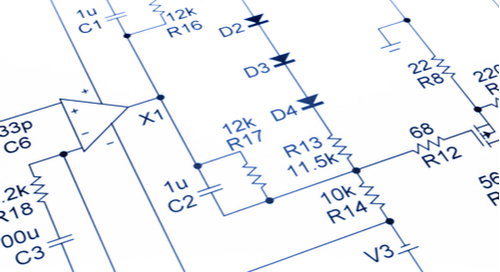
The next stage involves translating the idea of the design onto a schematic. You’ll be connecting components in a way that makes the circuit functional. If you’re working on a complicated design involving hundreds of components, it’s wise to separate the design into modules or subcircuits.

PCB Layout
Once you’ve had every connection checked on the schematic, you’ll initiate the PCB layout by transferring the components over. PCB layout can be overwhelming for newbie PCB designers as there are so many areas that one must pay attention to.
You start by defining the PCB size, components arrangement, routing, and running a DRC to ensure none of the design rules are violated. Once you’re sure the PCB design is free from errors, you’ll need to generate the production files for fabrication and the Bill of Materials (BOM) for prototyping.
Prototyping
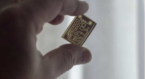
Prototyping involves fabricating the PCB, often in a small volume and assembling the components on it. Tests are carried out to ensure the PCB functions as required in the design spec. Any mistakes in the design must be documented for a revision. Else, a batch production is scheduled to manufacture the PCB in large numbers.
Electronic Circuit Design Best Practices For PCB Designers
Electronic Circuit Design Best Practices For PCB Designers
PCB designers play an important role in the process of electronic circuit design. An unforeseen mistake can sometimes make or break the prototype. Regardless of what design you’re working on, these tips will help you avoid potential heartaches.
PCB Space Allocation
The world is begging for smaller electronics. However, it is your responsibility to figure out what’s the minimum size of the PCB without compromising on factors like routability, interference, and heat dissipation.
If you’re working on Flex-PCB or enclosed-product, you’ll want to ensure that the design fits into the enclosure before producing the actual PCB. This means you’ll need to work closely with the mechanical engineers or product designers during the design phase.
 Space constraint is a common issue in PCB design
Components Placement
How you place the components on a PCB can result in very different outputs for the prototypes. For a start, analog components should have a reasonable clearance from their high-speed digital counterparts. The same applies to power management components, which should be grouped in a certain part of the PCB.
Besides functionality, component placement should take serviceability into account. This is true if you’re designing electronics for industrial controllers where regular maintenance is required. Ensure that wire-to-board connectors are placed strategically to make servicing and troubleshooting easier.
Electromagnetic Interference (EMI)
With lesser space, higher speed, and electronics going wireless, there is an increasing concern of EMI on PCB design. To reduce the possibility of your PCB being a source or affected by EMI, you’ll want to take note of the ground plane and current return path.
Having a good separation of ground planes, especially for high-speed signals help in minimizing interference that couple through the ground copper. Also, it’s important to ensure high-speed signals have the shortest return path to prevent the signal interfere with other components.
Power Delivery Network
No matter how sophisticated your design is, a bad power module design can render it dysfunctional. Besides choosing the right power regulating components or battery, you’ll want to ensure that the traces are sufficient for the current density.
A good power delivery network design ensures minimal power loss along the PCB, and sufficient power is delivered to all components on the board.
Printing that Printed Circuit Board Design
Printing that Printed Circuit Board Design
Importantly, in any PCB design, you’ll want to be sure that you are consistently thinking about the overall integrity of your production process. If you change a component in schematic, is that being modified later on and told to purchasing and mechanical teams? Has your circuit gone through verification yet and do you anticipate any hangups in verifying your circuit board design?
Electronic circuits are vitally sensitive, and in most cases, so is the team that designs them. Try and be the most considerate between ECAD and MCAD design teams by utilizing intuitive software that is capable of real-time updates and working through the particularly accurate documentation necessary for getting a design out the door.
Of course, it helps to design electronic circuits with quality PCB design software like OrCAD PCB designer. You’ll find that features like Cadence’s Analysis suite give you a good picture of the power delivery network in your PCB.
If you’re looking to learn more about how Cadence has the solution for you, talk to us and our team of experts.


Leave a Reply